The only Ring Circuit that you are likely to find in a domestic environment is that utilised by the sockets. The circuit is usually installed using 2.5mm² CSA Twin & Earth cable protected by a 30A MCB or re-wirable fuse or a 32A MCB. The cable leaves the fuse board and loops in and out of each socket and returns to the fuse board connecting to the same points in the fuse board as per the other end of the circuit. As many sockets as you like can form part of the ring circuit up to a maximum floor area of 100m². It is expected that a continuous current of 20A will be carried by the circuit and current in excess of this for short periods. Care should be taken with locating washing machines, dryers and dishwashers and spreading them out on the circuit. Consideration should also be given to providing a separate ring circuit for these appliances.
In older installations you will normally find a ring circuit supplying upstairs and another supplying downstairs. In modern installations it is normal to have an additional ring circuit to supply the kitchen, which is where one finds the heavier loads for, Kettles, Toasters, Washing Machines, Dishwashers, Grills etc. also in modern day ring circuits you will find the additional protection of an Residual Current Device (RCD). An RCD does not give overload protection like a fuse but gives quick protection if there should be a fault to earth, such as cutting a live cable or touching live parts. It is especially important to have one fitted to protect downstairs sockets where it could reasonably be expected to utilise them for portable equipment in the garden.
The diagram below shows a typical Ring Circuit
OLD COLOURS
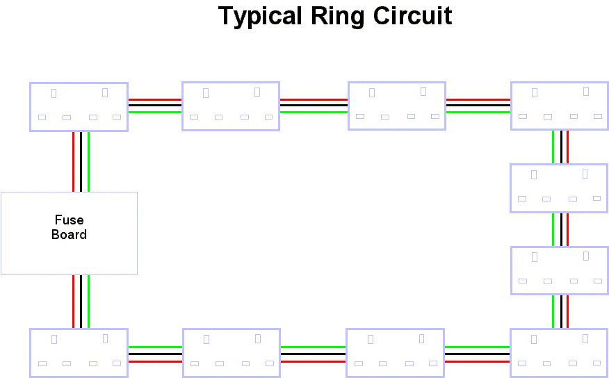
Click image to enlarge
(It will open in a new window)
REMEMBER GREEN REPRESENTS GREEN/YELLOW CONDUCTOR IDENTIFICATION
NEW COLOURS
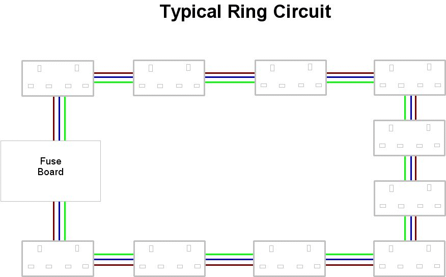
Click image to enlarge
(It will open in a new window)
REMEMBER GREEN REPRESENTS GREEN/YELLOW CONDUCTOR IDENTIFICATION
As previously mentioned, you can add addtional sockets to the ring circuit if they form part of the ring. You can also spur from each socket to one additional socket without providing any additional protection. One spur is permitted for each socket or two gang socket on the ring as shown in the diagram below.
OLD COLOURS
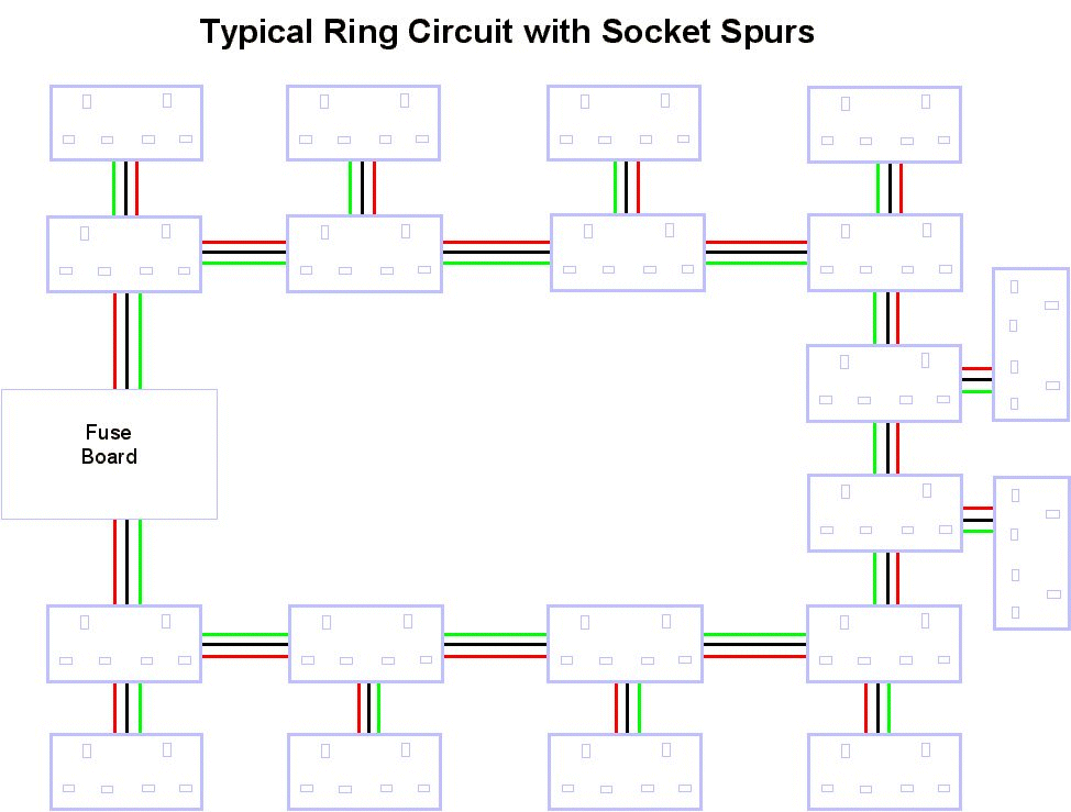
Click on image to enlarge
(It will open a new window)
REMEMBER GREEN REPRESENTS GREEN/YELLOW CONDUCTOR IDENTIFICATION
NEW COLOURS
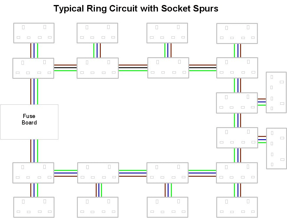
Click on image to enlarge
(It will open a new window)
REMEMBER GREEN REPRESENTS GREEN/YELLOW CONDUCTOR IDENTIFICATION
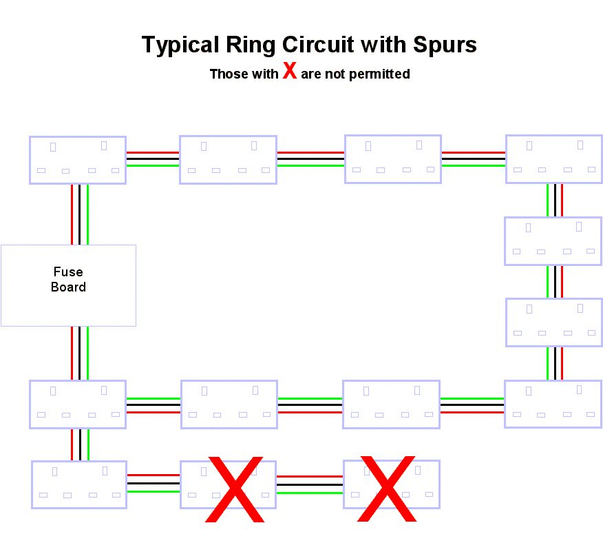
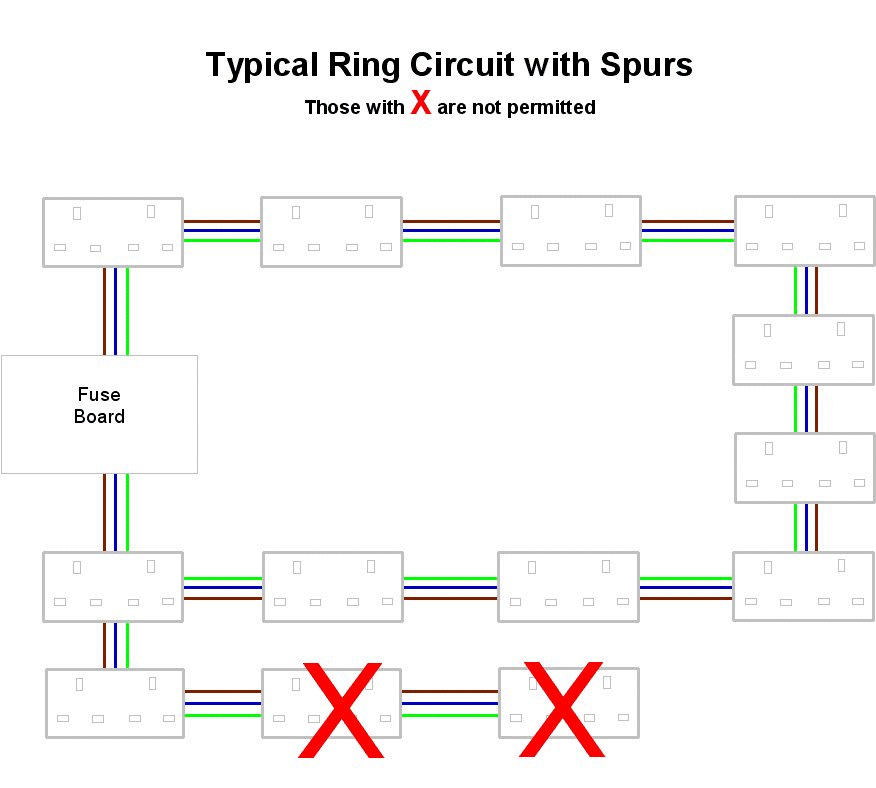
It is dangerous to install a spur from a spur unless the cable is of a suitable size that it can be suitably protected by the fuse protecting the circuit. This would require increasing the cable size to 4mm² Twin & Earth CSA. It is not good practice to mix cable sizes if it can be helped. The diagram below shows what NOT TO DO when 2.5mm² Twin and Earth cable is being used.
OLD COLOURS
Click image to enlarge
(It will open a new window)
REMEMBER GREEN REPRESENTS GREEN/YELLOW CONDUCTOR IDENTIFICATION
NEW COLOURS
Click image to enlarge
(It will open a new window)
REMEMBER GREEN REPRESENTS GREEN/YELLOW CONDUCTOR IDENTIFICATION
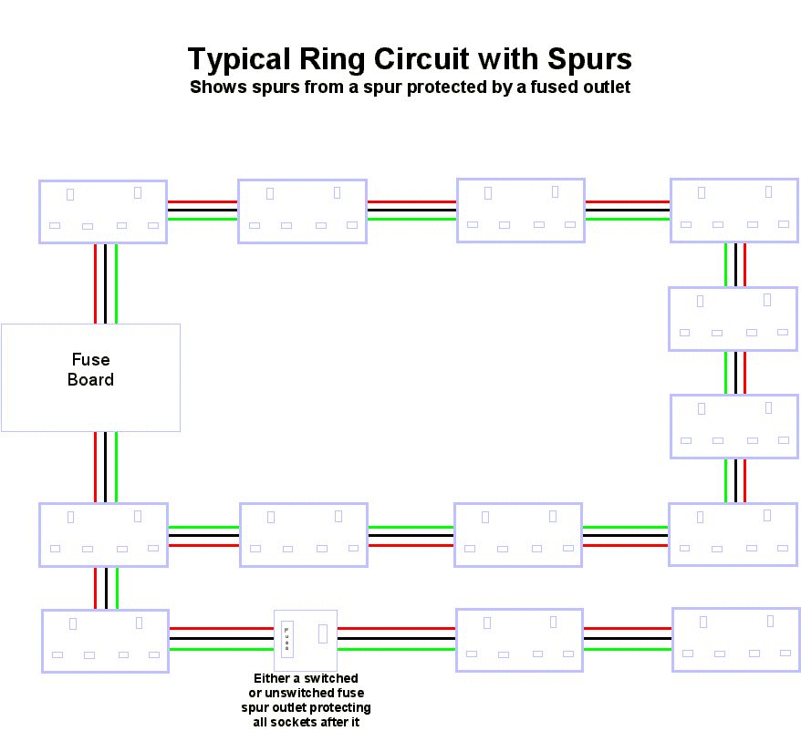
The diagram below shows a spur from a spur using 2.5mm² Twin & Earth CSA with suitable protection that limits the possible load to 13A which is the maximum fuse size that can be installed in a switched or unswitched fused spur. The cable is installed on the output side of the fused spur to protect all the sockets installed further up the circuit.
OLD COLOURS
Click on image to enlarge
(It will open in a new window)
REMEMBER GREEN REPRESENTS GREEN/YELLOW CONDUCTOR IDENTIFICATION
NEW COLOURS

Click on image to enlarge
(It will open in a new window)
REMEMBER GREEN REPRESENTS GREEN/YELLOW CONDUCTOR IDENTIFICATION
